

Robotic Friction Stir Welding: From Research Cell to Production
Robotic friction stir welding (FSW) places demanding forces on a robot, its tooling and the fixture holding the parts. On 24 September 2026, KUKA described a research cell at the Magdeburg-Stendal University of Applied Sciences in Germany, developed with KUKA Systems AWS. The project combines an industrial robot platform with FSW and milling research. Published 2026-10-31 04:04:03 -04:00 (America/New_York).
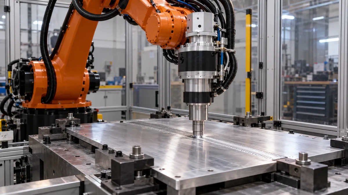
What the project is intended to investigate
KUKA identifies the robot in the cell as the KR FORTEC ultra MT, designed for applications requiring high process forces. The company says the platform combines welding and milling, with a digital twin and process-data capture to support planning and analysis. These are research and development capabilities; the announcement does not establish a validated production process for every material or component.
In friction stir welding, a rotating tool is pressed into and moved along the joint while the materials soften and mix. The process differs from conventional fusion welding, and the machine must withstand the forces involved. Material choice, joint geometry, tool design and clamping affect the result.
Start with the joint
A manufacturer considering a pilot should document the materials, thicknesses, joint configuration and required mechanical properties. Qualified welding and materials specialists should select appropriate tests and determine the applicable requirements for the end product. A sound-looking seam alone is not enough to establish that a joint meets its specification.
Provide the integrator with representative components, including normal variation in fit-up. Ask how the workpieces are located and restrained, where forces are transmitted, and whether fixtures permit inspection of the finished joint. Clamping design may be as important to the outcome as the robot's nominal payload.
Use simulation as a planning tool
A digital model can help examine reach, potential collisions and the sequence of operations before building a physical cell. It should be checked against the actual robot, tool, fixture and process conditions. Deviations in a physical installation, tool wear or part distortion can make a simulated path unsuitable without adjustment.
Agree what process data will be recorded and how they relate to inspection results. A pilot may track tool position, force and other relevant parameters, but the project team should define acceptable ranges through its own qualified process. Record program versions and tool changes so that a result can be traced back to the conditions used.
Plan the route to production
Acceptance should cover multiple representative joints and normal operating periods, not only a single demonstration. Measure good output, inspection failures, rework, tool life, changeover and downtime. Include the time required to load and unload the fixture and to recover safely after an interruption.
Budget for tooling, guarding, extraction where needed, training, maintenance and inspection alongside the robot. The university cell is a research platform; any claim about production savings or certification should be supported by evidence from the proposed application. Confirm local safety and product obligations with qualified professionals before commissioning.
Explore our supplier directory or contact the team with your joining application.